Learn About Different Types Of Hydraulic Vane Pumps
Details
| Date & time | Jun 22 '20 |
| Location | NO.118 Luxing Middle Road,Anzhou Street ,Xianju,Zhejiang,China |
| Creator | Cassidyvanepump |
Who's attending
Description
In a vane pump, a slotted rotor splined to the drive shaft rotates between tightly fitting side plates inside an oval or circular ring. The polished, hardened blades slide in and out of the rotor slots and follow the circular contour under the action of centrifugal force. A pump chamber is formed between the subsequent blades to transfer oil from the inlet to the outlet. As the spacing between the blades increases, a partial vacuum will be created at the entrance. As the size of the pump chamber decreases, the oil is squeezed out at the outlet.
Since the normal wear point of the hydraulic vane pump is the surface of the blade tip and ring, the blade and ring undergo special hardening and grinding. The vane pump is the only design with automatic wear compensation. As wear occurs, the blades only slip farther out of the rotor slot and continue to follow the contour of the ring. Therefore, the efficiency is always high throughout the life of the pump.
The displacement of the hydraulic vane pump depends on the width of the ring and rotor and the stroke of the cam ring. The interchangeable ring design allows the basic pump to be converted into multiple displacements. The vane pumps of balanced design are of fixed displacement. Unbalanced designs can be built in fixed displacement pumps or variable displacement pumps. If the correct oil is used to run in a clean system, the vane pump has good efficiency and durability. They cover low and medium pressure, capacity and speed ranges. The package size is small relative to the output. The vane pump is usually quiet, but it will run at high speed.
b. Unbalanced vane pump. In an unbalanced design, the shape of the cam ring is a true circle, and its center line is different from the center line of the rotor. The pump displacement depends on the eccentric distance between the rotor and the ring. The advantage of a true ring is that it can be applied to change the eccentricity and thus the displacement. The disadvantage is that the pressure imbalance at the outlet will effectively resist a small area of the rotor edge, thus exerting a lateral load on the shaft. Therefore, unless very large hearing and heavy supports are used, there will be restrictions on the size of the pump.
C. Balance vane pump. In a balanced design, the pump has a fixed oval cam
ring and two sets of internal ports. An evacuation chamber is formed between any
two blades twice per revolution. The two inlets and outlets are 180 degrees
apart. The back pressure on the rotor edge cancels each other out. Recent design
improvements allow higher operating speeds and pressures, making this pump the
most versatile pump in the mobile equipment field.
d. Double pump. The vane double pump is composed of two independent pump devices. Each component is contained in its own housing, which is installed in series and driven by a common shaft. Each pump also has its own inlet and outlet, which can be combined using manifolds or pipes. Two designs are provided, where two ink cartridges are housed in one main body. Sometimes an additional pump is installed at the head end to provide auxiliary flow requirements.
Dual pumps can be used to provide fluid flow for two separate circuits, or combined to meet the flow requirements of a single circuit. The delivery capacity of the combined pump will not change the maximum pressure rating of any filter element. Separate circuits require separate pressure control to limit the maximum pressure in each circuit.
A device is shown in which dual pumps are used to provide fluid flow for rapid advancement and feed of cylinders. In circuit B, two safety valves are used to control the operation of the pump. In circuit A, a safety valve and an unloading valve are used to control the pumping operation. In these two circuits, the delivery of the pump core is combined after passing through the valve. This combined flow is directed to the four-way valve and the rest of the circuit.
In circuit B, when the cylinder rod reaches and trips the pilot valve, the upper safety valve is vented. The exhaust safety valve can freely send the shaft end pump filter cartridge back to the oil tank. The maximum pressure of the control circuit of the other safety valve. The unloading valve and safety valve in circuit A perform the same operation. The outputs of the two pump boxes are combined to supply fluid for the fast-forward part of the cycle. When the output of one circuit returns to the tank, after reaching a certain point in the cycle, the other circuit completes the advance portion of the cycle. Then combine the output of the two pumps to return quickly.
e. Two-stage pump. The two-stage pump consists of two independent pump assemblies housed in a housing. The pump assembly is connected so that the flow from the outlet of one pump is internally directed to the inlet of the other pump. A single inlet and outlet are used for system connection. Structurally, the pump consists of individual pump cores, which are driven by a common drive shaft contained in a housing. The diverter valve is used to balance the pressure load on each stage and to correct small flow differences from any spool.
In operation, the developer flow rate of each filter cartridge is the same as a single pump. Figure 3-13 shows the fluid flow in a vane two-stage pump. The oil from the oil storage tank enters the inlet of the pump and then flows to the outlet of the first-stage pump box. (The channel in the pump body transports the effluent from this stage to the inlet of the second stage.) The outlet channel of the second stage directs oil to the outlet of the pump. The channel U connects the two chambers on the inlet side of the secondary pump and ensures that the pressure in the two chambers is equal. (Pressure is the pressure applied to the pump from an external source.)
The diverter valve consists of sliding pistons A and B. Piston A is subjected
to outlet pressure through channel V. Piston B bears the pressure between stages
through the channel W. The piston responds to maintain the pressure load. The
pressure on the primary pump is equal to half the outlet pressure of the
secondary pump. If from
The first stage exceeds the acceptable volume of the
second stage, and a pressure rise occurs in the channel W. The unbalanced force
acting on the piston B moves the piston so that excess oil flows through the
piston B through the channel B to reach the piston B. The entrance chamber of
the primary filter cartridge. The fluid throttled by the piston B can maintain
the pressure in the channel V.
If the discharge flow of the first-stage pump is less than the flow required by the second-stage pump, the pressure at the piston B decreases. The unbalanced force acting on piston A causes the piston to move, causing oil to flow through piston A into channels X and W to supplement the second-stage pump and correct the imbalance. Channels Z and Y provide a means for leaking around the piston to return to the inlet chamber of the first stage pump. Pistons A and B always look for a position to distribute the load evenly between the two pump units.
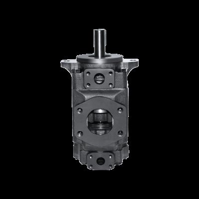
Zhejiang Yongling Hydraulic Machine Co , Ltd . is a large China
manufacturer and supplier of Hydraulic Vane Pumps . V/Vq Series Vane Pumps have
unique filter element design in the vanes, and have the characteristics of
maintainability, high efficiency and long service life. It is suitable for
industry; T series high-pressure needle pump is a high-performance, low-cost
pump. Balanced design and lip blade technology are key features. Follow us for
product details and technical information: https://www.china-vanepump.com/

The Wall